Product Description
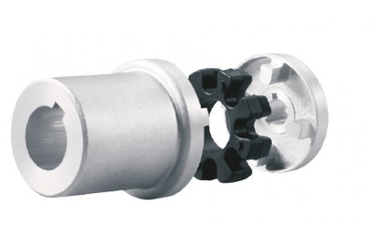
GIICLZ Type Drum Gear Coupling(JB/T 8854.2-2001)
♦Description
GIICLZ drum-shaped gear coupling has the relative offset performance of 2 axes compensated in a certain angle direction and works long distances with the middle axle. It is suitable for connecting horizontal 2 coaxial lines with a certain angular displacement of the transmission shafting.
♦Features
1. Small radial dimension and large bearing capacity are commonly used in shafting transmission under low speed and heavy load conditions.
2. Under the same outer diameter of the inner gear sleeve and the maximum outer diameter of the coupling, the load-carrying capacity of the drum-shaped gear coupling is 15-20% higher than that of the straight-tooth coupling on average.
3. It can compensate for the relative offset of 2 axes at a certain angle and work long distances with the middle axle.
4. It is suitable for connecting horizontal 2 coaxial axes and driving shafting with a certain angle displacement.
♦Main Dimension and Parameter
| Type |
Nominal torque (kN·m) |
Allowable speed (R/min) |
Shaft hole diameter | Shaft hole length | D | D1 | D2 | D3 | C | H | A | B | e | Rotary inertia Kg.m2 |
Weight | ||
| d1 | d2 | Y | J1type | ||||||||||||||
| GIICLZ1 | 0.4 | 4000 | 30 | 35 | 82 | 60 | 103 | 71 | 71 | 50 | 8 | 2 | 18 | 38 | 38 | 0.005 | 4.1 |
| GIICLZ2 | 0.71 | 4000 | 25 | 28 | 62 | 44 | 115 | 83 | 83 | 60 | 8 | 2 | 21 | 44 | 42 | 0.00625 | 4.8 |
| GIICLZ3 | 1.12 | 4000 | 25 | 28 | 62 | 44 | 127 | 95 | 95 | 75 | 8 | 2 | 22 | 45 | 42 | 0.011 | 7.8 |
| GIICLZ4 | 1.8 | 4000 | 63 | 65 | 142 | 107 | 149 | 116 | 116 | 90 | 8 | 2 | 24.5 | 49 | 42 | 0.039 | 16.5 |
| GIICLZ5 | 3.15 | 4000 | 63 | 65 | 142 | 107 | 167 | 134 | 134 | 105 | 10 | 2.5 | 27.5 | 54 | 42 | 0.5175 | 23.1 |
| GIICLZ6 | 5 | 4000 | 80 | 85 | 172 | 132 | 187 | 187 | 187 | 153 | 10 | 2.5 | 28 | 55 | 42 | 0.10425 | 35.4 |
| GIICLZ7 | 7.1 | 3750 | 100 | 105 | 212 | 167 | 204 | 170 | 170 | 140 | 10 | 2.5 | 30 | 59 | 42 | 0.1898 | 54.3 |
| GIICLZ8 | 10 | 3300 | 100 | 110 | 212 | 167 | 230 | 186 | 186 | 155 | 12 | 3 | 33.5 | 71 | 47 | 0.297 | 67.4 |
| GIICLZ9 | 16 | 3000 | 130 | 135 | 252 | 202 | 256 | 222 | 212 | 180 | 12 | 3 | 34.5 | 37 | 47 | 0.575 | 104.4 |
| GIICLZ10 | 22.4 | 2650 | 130 | 145 | 252 | 202 | 287 | 239 | 239 | 200 | 14 | 3.5 | 39 | 82 | 47 | 0.935 | 133.5 |
| GIICLZ11 | 35.5 | 2350 | 160 | 170 | 302 | 242 | 325 | 250 | 250 | 235 | 14 | 3.5 | 40.5 | 85 | 47 | 1.625 | 193 |
| GIICLZ12 | 50 | 2100 | 190 | 200 | 325 | 282 | 362 | 286 | 313 | 270 | 16 | 4.0 | 44.5 | 95 | 49 | 3.093 | 290 |
| GIICLZ13 | 71 | 1850 | 200 | 220 | 352 | 282 | 412 | 322 | 350 | 300 | 18 | 4.5 | 49 | 104 | 49 | 6.34 | 370 |
| GIICLZ14 | 112 | 1650 | 240 | 250 | 470 | 330 | 462 | 420 | 335 | 380 | 22 | 5.5 | 86 | 148 | 63 | 8.6 | 509 |
| GIICLZ15 | 180 | 1500 | 280 | 285 | 470 | 380 | 512 | 470 | 380 | 380 | 22 | 5.5 | 91 | 158 | 63 | 15.575 | 740 |
| GIICLZ16 | 250 | 1300 | 280 | 300 | 470 | 380 | 580 | 522 | 430 | 430 | 28 | 7 | 104.5 | 177 | 67 | 26.35 | 974 |
| GIICLZ17 | 355 | 1200 | 250 | 260 | 410 | 330 | 644 | 582 | 490 | – | 28 | 7 | 99 | 182 | 67 | 38.825 | 1110 |
| GIICLZ18 | 500 | 1050 | 340 | 360 | 550 | 450 | 726 | 658 | 540 | – | 28 | 8 | 111 | 215 | 75 | 49.5 | 1465 |
| GIICLZ19 | 710 | 950 | 340 | 320 | 470 | 380 | 818 | 748 | 630 | – | 32 | 8 | 116 | 220 | 75 | 139.5 | 2457 |
| GIICLZ20 | 1000 | 800 | 480 | 500 | 650 | 540 | 928 | 838 | 720 | – | 32 | 10.5 | 123.5 | 235 | 75 | 277.25 | 3793 |
| GIICLZ21 | 1400 | 750 | 480 | 500 | 650 | 540 | 1571 | 928 | 810 | – | 40 | 11.5 | 127.5 | 245 | 75 | 435 | 4780 |
| GIICLZ22 | 1800 | 650 | 670 | 680 | 900 | 780 | 1134 | 1036 | 915 | – | 40 | 13 | 131 | 255 | 75 | 852.25 | 7540 |
| GIICLZ23 | 2500 | 600 | 670 | 710 | 900 | 780 | 1282 | 1178 | 1030 | – | 50 | 14.5 | 149.5 | 290 | 80 | 1638.75 | 11133 |
| GIICLZ24 | 3550 | 550 | 800 | 850 | 1000 | 880 | 1428 | 1322 | 1175 | – | 50 | 16.5 | 158.5 | 305 | 80 | 2976.25 | 16110 |
| GIICLZ25 | 4500 | 460 | 1000 | 1040 | – | 1100 | 1644 | 1538 | 1390 | – | 50 | 19 | 162.5 | 310 | 80 | 7198.25 | 27797 |
Note:
The moment of inertia and mass are calculated according to and including J1 axial extension.
2. The axle hole size marked “*” in the axle hole diameter column is only applicable to d1 selection.
3. J1 shaft extension series is recommended.
4. The axle hole diameter with brackets is not used in the new design.
♦Packaging & Shipping
Other products
♦Other Products List
| Transmission Machinery Parts Name |
Model |
| Universal Coupling | WS,WSD,WSP |
| Cardan Shaft | SWC,SWP,SWZ |
| Tooth Coupling | CL,CLZ,GCLD,GIICL, GICL,NGCL,GGCL,GCLK |
| Disc Coupling | JMI,JMIJ,JMII,JMIIJ |
| High Flexible Coupling | LM |
| Chain Coupling | GL |
| Jaw Coupling | LT |
| Grid Coupling | JS |
Company Profile
♦Our Company
HangZhou CHINAMFG Machinery Manufacturing Co., Ltd. is a high-tech enterprise specializing in the design and manufacture of various types of coupling. There are 26 employees in our company, including 2 senior engineers and no fewer than 20 mechanical design and manufacture, heat treatment, welding, and other professionals.
Advanced and reasonable process, complete detection means. Our company actively introduces foreign advanced technology and equipment, on the basis of the condition, we make full use of the advantage and do more research and innovation. Strict to high quality and operate strictly in accordance with the ISO9000 quality certification system standard mode.
Our company supplies different kinds of products. High quality and reasonable price. We stick to the principle of “quality first, service first, continuous improvement and innovation to meet the customers” for the management and “zero defect, zero complaints” as the quality objective.
♦Our Services
1. Design Services
Our design team has experience in Cardan shafts relating to product design and development. If you have any needs for your new product or wish to make further improvements, we are here to offer our support.
2. Product Services
Raw materials → Cutting → Forging →Rough machining →Shot blasting →Heat treatment →Testing →Fashioning →Cleaning→ Assembly→ Packing→ Shipping
3. Samples Procedure
We could develop the sample according to your requirement and amend the sample constantly to meet your need.
4. Research & Development
We usually research the new needs of the market and develop the new model when there is new cars in the market.
5. Quality Control
Every step should be a special test by Professional Staff according to the standard of ISO9001 and TS16949.
♦FAQ
Q 1: Are you a trading company or a manufacturer?
A: We are a professional manufacturer specializing in manufacturing various series of couplings.
Q 2: Can you do OEM?
Yes, we can. We can do OEM & ODM for all the customers with customized artworks in PDF or AI format.
Q 3: How long is your delivery time?
Generally, it is 20-30 days if the goods are not in stock. It is according to quantity.
Q 4: Do you provide samples? Is it free or extra?
Yes, we could offer the sample but not for free. Actually, we have a very good price principle, when you make the bulk order the cost of the sample will be deducted.
Q 5: How long is your warranty?
A: Our Warranty is 12 months under normal circumstances.
Q 6: What is the MOQ?
A: Usually our MOQ is 1 pcs.
Q 7: Do you have inspection procedures for coupling?
A: 100% self-inspection before packing.
Q 8: Can I have a visit to your factory before the order?
A: Sure, welcome to visit our factory.
Q 9: What’s your payment?
A: T/T.
♦Contact Us
Web: huadingcoupling
Add: No.11 HangZhou Road,Chengnan park,HangZhou City,ZheJiang Province,China
/* January 22, 2571 19:08:37 */!function(){function s(e,r){var a,o={};try{e&&e.split(“,”).forEach(function(e,t){e&&(a=e.match(/(.*?):(.*)$/))&&1

Do Drive Couplings Require Periodic Lubrication, and If So, How Often?
Yes, drive couplings often require periodic lubrication to ensure smooth and efficient operation. The frequency of lubrication depends on the type of coupling and the specific application. Here are some general guidelines for lubricating drive couplings:
- Flexible Couplings: Most flexible drive couplings, such as elastomeric and grid couplings, do not require frequent lubrication. These couplings typically utilize elastomeric materials or grid elements that do not need lubrication. However, it is essential to inspect the coupling regularly for signs of wear or damage and lubricate any movable components if necessary. Consult the manufacturer’s guidelines for specific lubrication recommendations.
- Gear Couplings: Gear couplings, which use gear teeth to transmit torque, require periodic lubrication. The lubrication interval depends on factors like the coupling size, operating conditions, and the type of lubricant used. In many cases, gear couplings require lubrication every 3 to 6 months or after a certain number of operating hours. Regular inspections should be carried out to check the lubricant’s condition and replenish it as needed.
- Chain Couplings: Chain couplings, which employ roller chains, necessitate regular lubrication to reduce friction and wear. The frequency of lubrication can vary based on the chain type, speed, and operating conditions. Some chains require lubrication every 1 to 3 months, while others may need more frequent attention. Proper lubrication helps extend the chain’s life and maintain the coupling’s efficiency.
When applying lubrication to drive couplings, it is essential to use the recommended lubricant specified by the manufacturer. The lubricant’s properties, such as viscosity and temperature range, should align with the coupling’s requirements and the application’s operating conditions. Over-lubrication can be as detrimental as under-lubrication, so it’s crucial to adhere to the recommended lubrication amounts.
In summary, drive couplings may require periodic lubrication depending on their type and design. Following the manufacturer’s recommendations for lubrication intervals and using the appropriate lubricant helps ensure the drive coupling operates smoothly and efficiently throughout its service life.
Can Drive Couplings Compensate for Misalignments in Shafts?
Yes, drive couplings are designed to compensate for certain degrees of misalignment between shafts in mechanical power transmission systems. The ability of a coupling to accommodate misalignments depends on its type and design. Here are the common types of misalignments and the corresponding coupling types that can handle them:
- Parallel Misalignment: This type of misalignment occurs when the axes of the two shafts are parallel but not perfectly aligned. Elastomeric couplings, such as jaw couplings and tire couplings, are commonly used to handle parallel misalignment. These couplings have flexible elements that can offset slight parallel offsets between the shafts.
- Angular Misalignment: Angular misalignment refers to the situation where the axes of the two shafts are not collinear and form an angle. Flexible couplings like beam couplings and Oldham couplings are effective in accommodating angular misalignment. They have a design that allows for relative movement between the shafts while transmitting torque.
- Radial Misalignment: Radial misalignment occurs when there is a gap between the axes of the two shafts. Flexible couplings with multiple elements, such as disc couplings and grid couplings, can handle radial misalignment to some extent. These couplings use flexible components to allow relative movement between the shafts.
- Combination Misalignment: Some couplings, like universal joint couplings and double loop couplings, are designed to compensate for multiple types of misalignments simultaneously. These couplings are suitable for applications where complex misalignments exist.
It’s important to note that while drive couplings can compensate for certain degrees of misalignment, they have their limitations. Excessive misalignment or misalignments beyond their design capabilities can lead to premature wear, reduced coupling life, and decreased efficiency in power transmission. Proper alignment during installation is still essential to ensure the longevity and optimal performance of the coupling and the entire power transmission system.
When selecting a drive coupling for an application with misalignment concerns, it is crucial to consider the type and magnitude of misalignment expected and choose a coupling that can handle it effectively while still meeting other performance requirements.
How to Diagnose and Fix Common Problems with Drive Couplings?
Drive couplings, like any mechanical component, can experience issues over time. Diagnosing and fixing these problems promptly is essential to ensure the proper functioning of the power transmission system and prevent further damage. Here’s a step-by-step guide to diagnose and fix common problems with drive couplings:
- Visual Inspection: Start by visually inspecting the drive coupling and surrounding components. Look for signs of wear, cracks, or damage in the coupling’s flexible elements, bolts, and connections.
- Check for Misalignment: Misalignment is a common cause of drive coupling problems. Use alignment tools to check if the shafts connected by the coupling are properly aligned. Misalignment can lead to premature wear and vibration issues.
- Listen for Unusual Noises: Unusual noises like clunking, rattling, or grinding may indicate problems with the drive coupling. Pay attention to any sounds while the vehicle is in motion.
- Inspect for Fluid Leaks: Check for any transmission fluid leaks around the drive coupling area. Fluid leaks can lead to insufficient lubrication and cause further damage.
- Test for Slippage: Slippage can occur if the drive coupling is not securely transmitting power. Perform tests to see if the transmission slips out of gear or has difficulty engaging.
- Monitor Power Loss: If the vehicle experiences power loss or reduced acceleration, it may be due to a faulty drive coupling. Monitor the engine’s performance and power delivery.
- Inspect Bolts and Fasteners: Loose or worn bolts and fasteners can lead to coupling problems. Check and tighten all connections as needed.
- Examine Torsional Flexibility: For flexible drive couplings, assess the torsional flexibility to ensure it can accommodate torque fluctuations and prevent damage from torque spikes.
- Replace Damaged Coupling: If you find any issues with the drive coupling during inspection, replace the damaged coupling with a new one that matches the required specifications.
- Realign Shafts: If misalignment is detected, realign the shafts to the manufacturer’s recommended tolerances. Proper alignment will help prevent future problems.
- Lubricate as Needed: Some drive couplings require periodic lubrication. Ensure that the coupling is adequately lubricated as per the manufacturer’s guidelines.
- Perform Test Runs: After fixing the drive coupling or making adjustments, perform test runs to ensure that the transmission functions smoothly and there are no unusual noises or vibrations.
It’s essential to follow the manufacturer’s guidelines and maintenance schedules for the specific drive coupling used in your vehicle. Regular maintenance and inspections can help identify and address potential problems early, preventing costly repairs and ensuring the longevity of the power transmission system.


editor by CX 2024-05-09
by
Tags:
Leave a Reply