Product Description
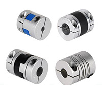
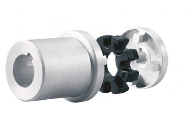
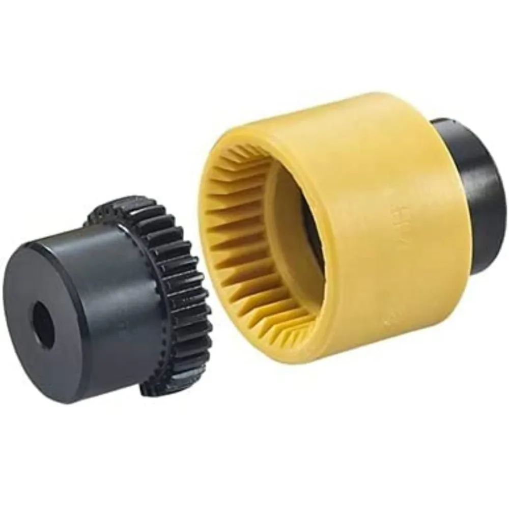
Stainless Steel Gear Roller Chain Mechanical Power Transmission Drive Parts Components Connection Tyre Grid Jaw Spider Fan Pump Rubber Coupler Manufacturer Round Motor Shaft Price Universal Joint Coupling
Features
1. Compact designing, easy installation.
2. Convenient maintenance, small size, and lightweight.
3. Absorb the transmission of impact load.
4. Prevent overload.
We can provide the following couplings:
| Rigid coupling | Flange coupling | Oldham coupling |
| Chain Coupling | HRC Coupling | Jaw Coupling |
| Sleeve or muff coupling | Gear coupling | Bellow coupling |
| Split muff coupling | Flexible coupling | Fluid coupling |
| Spacer Coupling | Nm Coupling | MH Coupling |
| Clamp or split-muff or compression coupling | Universal coupling | Variable speed coupling |
| Bushed pin-type coupling | Diaphragm coupling | Constant speed coupling |
Product Description
| SIZE | N.m | r/min |
D | D1 | d1 | L | C | n-M | kg | |
| FCL90 | 4 | 4000 | 90 | 35.5 | 11 | 28 | 3 | 4-M8 | 1.7 | |
| FCL100 | 10 | 4000 | 100 | 40 | 11 | 35.5 | 3 | 4-M10 | 2.3 | |
| FCL112 | 16 | 4000 | 112 | 45 | 13 | 40 | 3 | 4-M10 | 2.8 | |
| FCL125 | 25 | 4000 | 125 | 65 | 50 | 13 | 45 | 3 | 4-M12 | 4 |
| FCL140 | 50 | 4000 | 140 | 71 | 63 | 13 | 50 | 3 | 6-M12 | 5.4 |
| FCL160 | 110 | 4000 | 160 | 80 | 15 | 56 | 3 | 8-M12 | 8 | |
| FCL180 | 157 | 3500 | 180 | 90 | 15 | 63 | 3 | 8-M12 | 10.5 | |
| FCL200 | 245 | 3200 | 200 | 100 | 21 | 71 | 4 | 8-M20 | 16.2 | |
| FCL224 | 392 | 2850 | 224 | 112 | 21 | 80 | 4 | 8-M20 | 21.3 | |
| FCL250 | 618 | 2550 | 250 | 125 | 25 | 90 | 4 | 8-M24 | 31.6 | |
| FCL280 | 980 | 2300 | 280 | 140 | 34 | 100 | 4 | 8-M24 | 44 | |
| FCL315 | 1568 | 2050 | 315 | 160 | 41 | 112 | 4 | 10-M24 | 57.7 | |
| FCL355 | 2450 | 1800 | 355 | 180 | 60 | 125 | 5 | 8-M30 | 89.5 | |
| FCL400 | 3920 | 1600 | 400 | 200 | 60 | 125 | 5 | 10-M30 | 113 | |
| FCL450 | 6174 | 1400 | 450 | 224 | 65 | 140 | 5 | 12-M30 | 145 | |
| FCL560 | 9800 | 1150 | 560 | 250 | 85 | 160 | 5 | 14-M30 | 229 | |
| FCL630 | 15680 | 1000 | 630 | 280 | 95 | 180 | 5 | 18-M30 | 296 | |
Related Products
Company Profile
FAQ
Q: How to ship the coupling to us?
A: It is available by air, sea, or train.
Q: How to pay the money?
A: T/T and L/C are preferred, with different currencies, including USD, EUR, RMB, etc.
Q: How can I know if the product is suitable for me?
A: >1ST confirm drawing and specification >2nd test sample >3rd start mass production.
Q: Can I come to your company to visit?
A: Yes, you are welcome to visit us at any time.
/* January 22, 2571 19:08:37 */!function(){function s(e,r){var a,o={};try{e&&e.split(“,”).forEach(function(e,t){e&&(a=e.match(/(.*?):(.*)$/))&&1
What are the Temperature and Speed Limits for Different Drive Coupling Types?
The temperature and speed limits for different drive coupling types vary based on their design, materials, and intended applications. Here are some general guidelines for temperature and speed limits for common drive coupling types:
- Elastomeric Couplings: Elastomeric couplings, which use rubber or elastomer elements, typically have temperature limits ranging from -40°C to 120°C (-40°F to 248°F). The speed limits for elastomeric couplings are generally up to 5000 RPM, but this can vary depending on the coupling size and design.
- Grid Couplings: Grid couplings are designed to handle higher torque and speed requirements. They often have temperature limits between -20°C to 100°C (-4°F to 212°F). The speed limits for grid couplings can range from 5000 to 8000 RPM, depending on the coupling size and grid material.
- Gear Couplings: Gear couplings are known for their high torque capacity and can operate at higher temperatures. Their temperature limits typically range from -20°C to 150°C (-4°F to 302°F). The speed limits for gear couplings can vary widely based on the coupling’s size and design, with some models capable of operating at speeds up to 10,000 RPM or higher.
- Chain Couplings: Chain couplings are suitable for heavy-duty applications. They often have temperature limits between -20°C to 150°C (-4°F to 302°F) depending on the chain material. The speed limits for chain couplings can range from 1500 to 6000 RPM, depending on the chain type and size.
It’s essential to consider the operating environment, load conditions, and coupling material when determining the suitable temperature and speed limits for a specific application. Exceeding the recommended limits can lead to premature wear, reduced performance, and potential coupling failure.
Manufacturers of drive couplings provide detailed specifications and operating guidelines for their products. It’s crucial to consult the manufacturer’s documentation to ensure that the selected coupling is suitable for the intended application and operating conditions.
Can Drive Couplings Compensate for Misalignments in Shafts?
Yes, drive couplings are designed to compensate for certain degrees of misalignment between shafts in mechanical power transmission systems. The ability of a coupling to accommodate misalignments depends on its type and design. Here are the common types of misalignments and the corresponding coupling types that can handle them:
- Parallel Misalignment: This type of misalignment occurs when the axes of the two shafts are parallel but not perfectly aligned. Elastomeric couplings, such as jaw couplings and tire couplings, are commonly used to handle parallel misalignment. These couplings have flexible elements that can offset slight parallel offsets between the shafts.
- Angular Misalignment: Angular misalignment refers to the situation where the axes of the two shafts are not collinear and form an angle. Flexible couplings like beam couplings and Oldham couplings are effective in accommodating angular misalignment. They have a design that allows for relative movement between the shafts while transmitting torque.
- Radial Misalignment: Radial misalignment occurs when there is a gap between the axes of the two shafts. Flexible couplings with multiple elements, such as disc couplings and grid couplings, can handle radial misalignment to some extent. These couplings use flexible components to allow relative movement between the shafts.
- Combination Misalignment: Some couplings, like universal joint couplings and double loop couplings, are designed to compensate for multiple types of misalignments simultaneously. These couplings are suitable for applications where complex misalignments exist.
It’s important to note that while drive couplings can compensate for certain degrees of misalignment, they have their limitations. Excessive misalignment or misalignments beyond their design capabilities can lead to premature wear, reduced coupling life, and decreased efficiency in power transmission. Proper alignment during installation is still essential to ensure the longevity and optimal performance of the coupling and the entire power transmission system.
When selecting a drive coupling for an application with misalignment concerns, it is crucial to consider the type and magnitude of misalignment expected and choose a coupling that can handle it effectively while still meeting other performance requirements.
How to Diagnose and Fix Common Problems with Drive Couplings?
Drive couplings, like any mechanical component, can experience issues over time. Diagnosing and fixing these problems promptly is essential to ensure the proper functioning of the power transmission system and prevent further damage. Here’s a step-by-step guide to diagnose and fix common problems with drive couplings:
- Visual Inspection: Start by visually inspecting the drive coupling and surrounding components. Look for signs of wear, cracks, or damage in the coupling’s flexible elements, bolts, and connections.
- Check for Misalignment: Misalignment is a common cause of drive coupling problems. Use alignment tools to check if the shafts connected by the coupling are properly aligned. Misalignment can lead to premature wear and vibration issues.
- Listen for Unusual Noises: Unusual noises like clunking, rattling, or grinding may indicate problems with the drive coupling. Pay attention to any sounds while the vehicle is in motion.
- Inspect for Fluid Leaks: Check for any transmission fluid leaks around the drive coupling area. Fluid leaks can lead to insufficient lubrication and cause further damage.
- Test for Slippage: Slippage can occur if the drive coupling is not securely transmitting power. Perform tests to see if the transmission slips out of gear or has difficulty engaging.
- Monitor Power Loss: If the vehicle experiences power loss or reduced acceleration, it may be due to a faulty drive coupling. Monitor the engine’s performance and power delivery.
- Inspect Bolts and Fasteners: Loose or worn bolts and fasteners can lead to coupling problems. Check and tighten all connections as needed.
- Examine Torsional Flexibility: For flexible drive couplings, assess the torsional flexibility to ensure it can accommodate torque fluctuations and prevent damage from torque spikes.
- Replace Damaged Coupling: If you find any issues with the drive coupling during inspection, replace the damaged coupling with a new one that matches the required specifications.
- Realign Shafts: If misalignment is detected, realign the shafts to the manufacturer’s recommended tolerances. Proper alignment will help prevent future problems.
- Lubricate as Needed: Some drive couplings require periodic lubrication. Ensure that the coupling is adequately lubricated as per the manufacturer’s guidelines.
- Perform Test Runs: After fixing the drive coupling or making adjustments, perform test runs to ensure that the transmission functions smoothly and there are no unusual noises or vibrations.
It’s essential to follow the manufacturer’s guidelines and maintenance schedules for the specific drive coupling used in your vehicle. Regular maintenance and inspections can help identify and address potential problems early, preventing costly repairs and ensuring the longevity of the power transmission system.


editor by CX 2024-05-03
by
Tags:
Leave a Reply