Product Description
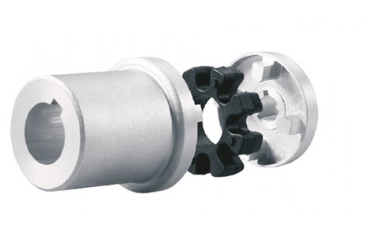
Drum shape gear coupling with brake wheel steel rigid shaft connection motor pump drive shaft Gear Coupling
Description:
WGP Drum Gear Coupling With Brake Disc has a brake disc, brake disc can rotate speed by controlling the speed to adjust the machine. As shown in figure WGP with brake drum set type gear coupling is divided into I type and II type 2 forms, the only difference is that the brake disc is different.
Characteristics:
1. Strong load-bearing capacity. Under the same outer diameter of the inner gear sleeve and the maximum outer diameter of the coupling, the bearing capacity of the drum gear coupling is increased by an average of 15-20% compared to the straight gear coupling;
2. The angular displacement compensation is large. When the radial displacement is equal to zero, the allowable angular
displacement of the straight tooth coupling is 1o, while the allowable angular displacement of the drum tooth coupling is 1o30 ‘, an increase of 50%. Under the same modulus, number of teeth, and tooth width, the allowable angular displacement of drum shaped teeth is greater than that of straight teeth;
3. The drum shaped tooth surface improves the contact conditions between the inner and outer teeth, avoiding the drawbacks of extrusion and stress concentration at the edge of straight teeth under angular displacement conditions. At the same time, it improves the friction and wear conditions of the tooth surface, reduces noise, and has a long maintenance cycle;
4. The outer gear sleeve has a CHINAMFG shaped tooth end, making it very convenient to assemble and disassemble the inner and outer teeth;
5. Transmission efficiency up to 99.7%;
Based on the above characteristics, drum shaped teeth have been widely used domestically and internationally to replace straight tooth couplings.
Paramaters:
Packing & shipping:
1 Prevent from damage.
2. As customers’ requirements, in perfect condition.
3. Delivery : As per contract delivery on time
4. Shipping : As per client request. We can accept CIF, Door to Door etc. or client authorized agent we supply all the necessary assistant.
FAQ:
Q 1: Are you a trading company or a manufacturer?
A: We are a professional manufacturer specializing in manufacturing various series of couplings.
Q 2:Can you do OEM?
Yes, we can. We can do OEM & ODM for all the customers with customized artworks in PDF or AI format.
Q 3:How long is your delivery time?
Generally, it is 20-30 days if the goods are not in stock. It is according to quantity.
Q 4: How long is your warranty?
A: Our Warranty is 12 months under normal circumstances.
Q 5: Do you have inspection procedures for coupling?
A:100% self-inspection before packing.
Q 6: Can I have a visit to your factory before the order?
A: Sure, welcome to visit our factory.
/* January 22, 2571 19:08:37 */!function(){function s(e,r){var a,o={};try{e&&e.split(“,”).forEach(function(e,t){e&&(a=e.match(/(.*?):(.*)$/))&&1
Can Drive Couplings Handle Reversing Loads and Shock Loads Effectively?
Yes, drive couplings are designed to handle reversing loads and shock loads effectively in various industrial applications. Their ability to accommodate these dynamic loads makes them suitable for many power transmission scenarios. Here’s how drive couplings handle reversing loads and shock loads:
- Reversing Loads: Drive couplings, especially flexible couplings like elastomeric, grid, and gear couplings, can handle reversing loads without difficulty. These couplings have torsional flexibility, which allows them to compensate for angular misalignments and absorb shocks during load reversals. As the direction of the load changes, the coupling flexes and adjusts accordingly, minimizing stress on the connected equipment. This flexibility also reduces the wear and tear on both the coupling and the connected machinery, leading to improved durability and extended service life.
- Shock Loads: Drive couplings are engineered to handle shock loads efficiently. Shock loads are sudden, high-intensity forces that can occur during equipment start-ups, stops, or unexpected changes in operating conditions. Elastomeric couplings are particularly effective in damping these shock loads due to the flexibility of their elastomeric elements. Grid couplings with a spring-like grid structure and gear couplings with rigid teeth also excel at distributing and absorbing shock loads. Even chain couplings, designed with roller chains, can effectively handle shock loads by absorbing the impact through the rollers and chain links.
When selecting a drive coupling for an application that involves reversing loads or shock loads, it’s essential to consider factors such as the magnitude and frequency of the loads, the operating environment, and the specific coupling’s design capabilities. Manufacturers often provide load capacity charts and guidelines to help users select the appropriate coupling for their requirements.
Proper maintenance and regular inspections are also essential to ensure that the coupling remains in good working condition. Monitoring the coupling’s performance and addressing any signs of wear or damage promptly can prevent unexpected failures and enhance the overall reliability of the power transmission system.
How to Select the Right Drive Coupling for Specific Torque and Speed Requirements
Choosing the appropriate drive coupling for specific torque and speed requirements is essential to ensure reliable and efficient power transmission in mechanical systems. Here are the steps to help you make the right selection:
- Identify Torque and Speed Parameters: Determine the maximum and minimum torque values that the coupling will experience during operation. Also, establish the required operating speed range.
- Consider the Application: Evaluate the application’s characteristics, such as the nature of the driven equipment, the presence of shock loads, vibrations, and misalignments. Different applications may require different coupling types and designs.
- Calculate Service Factor: Apply a service factor to the calculated torque to account for any variations in the load during operation. The service factor typically ranges from 1.2 to 2, depending on the application’s demands.
- Choose the Coupling Type: Based on the torque, speed, and application requirements, select the appropriate coupling type. Common coupling types include elastomeric couplings, grid couplings, gear couplings, and metallic disc couplings.
- Torsional Stiffness and Damping: Consider the desired level of torsional stiffness and damping based on the application’s need for rigidity and vibration absorption. High-speed applications may require couplings with good damping characteristics to prevent resonance.
- Temperature and Environment: Take into account the operating temperature and environmental conditions. Extreme temperatures or corrosive environments may require specific coupling materials or coatings.
- Alignment and Misalignment Tolerance: Assess the alignment capabilities of the coupling. Flexible couplings can accommodate misalignments, while rigid couplings require precise alignment.
- Space Limitations: Consider any spatial constraints for coupling installation. Some couplings may have compact designs suitable for confined spaces.
- Budget and Maintenance: Factor in the initial cost and ongoing maintenance requirements of the coupling. While some couplings may have higher upfront costs, they might offer longer service life and lower maintenance expenses.
- Consult with Manufacturers: Reach out to coupling manufacturers or specialists to discuss your specific requirements. They can provide expert advice and recommend suitable couplings for your application.
By carefully evaluating torque and speed requirements, considering the application’s characteristics, and selecting a coupling that matches the demands of the system, you can ensure optimal performance and longevity of the power transmission setup.
Can a Damaged Drive Coupling Lead to Transmission Issues in Vehicles?
Yes, a damaged drive coupling can lead to transmission issues in vehicles. Drive couplings are critical components that connect the engine to the transmission and other drivetrain components, allowing the transfer of power and torque. When a drive coupling is damaged or worn, it can negatively affect the performance and reliability of the entire transmission system. Here are some ways in which a damaged drive coupling can lead to transmission issues:
- Power Loss: A damaged drive coupling may not efficiently transfer power from the engine to the transmission. This can result in a loss of power, leading to reduced acceleration and overall vehicle performance.
- Transmission Slippage: When a drive coupling is damaged, it may not provide a secure connection between the engine and the transmission. This can lead to transmission slippage, where the transmission fails to engage properly, causing the vehicle to hesitate or slip out of gear while driving.
- Increased Transmission Wear: A damaged drive coupling can cause vibrations and misalignments in the drivetrain, leading to increased wear on the transmission components. Excessive wear can result in premature failure of transmission gears, bearings, and other critical parts.
- Difficulty in Shifting Gears: A faulty drive coupling may result in difficulty shifting gears, making it hard for the driver to smoothly transition between different gears. This can lead to jerky gear shifts and impact the vehicle’s overall drivability.
- Strange Noises: A damaged drive coupling may produce unusual noises, such as clunking, rattling, or grinding sounds, indicating a problem in the drivetrain. These noises can be a warning sign of potential transmission issues.
- Overheating Transmission: If a drive coupling is not functioning correctly, it may cause the transmission to work harder to compensate for the power loss. This increased workload can lead to overheating of the transmission fluid, potentially causing damage to internal components.
- Transmission Fluid Leaks: In some cases, a damaged drive coupling can cause leaks in the transmission system. Transmission fluid leaks can result in a loss of fluid, leading to decreased lubrication and potential damage to the transmission.
- Poor Fuel Efficiency: A malfunctioning drive coupling can contribute to poor fuel efficiency since the engine may not efficiently transfer power to the transmission and wheels, leading to increased fuel consumption.
It is essential to regularly inspect and maintain the drive coupling and other transmission components to prevent potential issues. If any signs of damage or wear are noticed, it is crucial to address the problem promptly and replace the damaged drive coupling to avoid further transmission problems and ensure the vehicle’s safe and smooth operation.


editor by CX 2024-04-22
by
Tags:
Leave a Reply