Product Description
Product Description
|
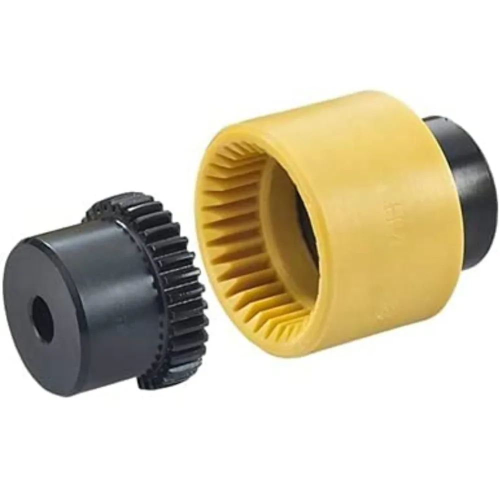
Product name |
Chain coupling |
|||
|
Material |
Carbon steel material |
|||
|
Structure |
Roller chain+sprocket+cover |
|||
|
Size |
KC3012, KC4012, KC4014, KC4016, KC5014, KC5016, KC5018, KC6018, KC6571, KC6571, KC8018, KC8571, KC8571, KC1571, KC12018, KC12571, KC16018, KC16571, KC20018, KC20571, KC24026 |
|||
|
Other type |
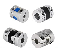
Flexible coupling |
|||
|
Application |
Shaft transmission |
|||
|
Feature |
High performance, light weight, convenient assembly |
|||
Packaging & Shipping
Company Profile
ZheJiang Haorongshengye Electrical Equipment Co., Ltd.
1. Was founded in 2008
2. Our Principle:
“Credibility Supremacy, and Customer First”
3. Our Promise:
“High quality products, and Excellent Service”
4. Our Value:
“Being Honesty, Doing the Best, and Long-lasting Development”
5. Our Aim:
“Develop to be a leader in the power transmission parts industry in the world”
|
6.Our services: |
1).Competitive price |
|||
|
2).High quality products |
||||
|
3).OEM service or can customized according to your drawings |
||||
|
4).Reply your inquiry in 24 hours |
||||
|
5).Professional technical team 24 hours online service |
||||
|
6).Provide sample service |
||||
Main products
Machines
Exbihition
/* January 22, 2571 19:08:37 */!function(){function s(e,r){var a,o={};try{e&&e.split(“,”).forEach(function(e,t){e&&(a=e.match(/(.*?):(.*)$/))&&1
What are the Temperature and Speed Limits for Different Drive Coupling Types?
The temperature and speed limits for different drive coupling types vary based on their design, materials, and intended applications. Here are some general guidelines for temperature and speed limits for common drive coupling types:
- Elastomeric Couplings: Elastomeric couplings, which use rubber or elastomer elements, typically have temperature limits ranging from -40°C to 120°C (-40°F to 248°F). The speed limits for elastomeric couplings are generally up to 5000 RPM, but this can vary depending on the coupling size and design.
- Grid Couplings: Grid couplings are designed to handle higher torque and speed requirements. They often have temperature limits between -20°C to 100°C (-4°F to 212°F). The speed limits for grid couplings can range from 5000 to 8000 RPM, depending on the coupling size and grid material.
- Gear Couplings: Gear couplings are known for their high torque capacity and can operate at higher temperatures. Their temperature limits typically range from -20°C to 150°C (-4°F to 302°F). The speed limits for gear couplings can vary widely based on the coupling’s size and design, with some models capable of operating at speeds up to 10,000 RPM or higher.
- Chain Couplings: Chain couplings are suitable for heavy-duty applications. They often have temperature limits between -20°C to 150°C (-4°F to 302°F) depending on the chain material. The speed limits for chain couplings can range from 1500 to 6000 RPM, depending on the chain type and size.
It’s essential to consider the operating environment, load conditions, and coupling material when determining the suitable temperature and speed limits for a specific application. Exceeding the recommended limits can lead to premature wear, reduced performance, and potential coupling failure.
Manufacturers of drive couplings provide detailed specifications and operating guidelines for their products. It’s crucial to consult the manufacturer’s documentation to ensure that the selected coupling is suitable for the intended application and operating conditions.
How to Select the Right Drive Coupling for Specific Torque and Speed Requirements
Choosing the appropriate drive coupling for specific torque and speed requirements is essential to ensure reliable and efficient power transmission in mechanical systems. Here are the steps to help you make the right selection:
- Identify Torque and Speed Parameters: Determine the maximum and minimum torque values that the coupling will experience during operation. Also, establish the required operating speed range.
- Consider the Application: Evaluate the application’s characteristics, such as the nature of the driven equipment, the presence of shock loads, vibrations, and misalignments. Different applications may require different coupling types and designs.
- Calculate Service Factor: Apply a service factor to the calculated torque to account for any variations in the load during operation. The service factor typically ranges from 1.2 to 2, depending on the application’s demands.
- Choose the Coupling Type: Based on the torque, speed, and application requirements, select the appropriate coupling type. Common coupling types include elastomeric couplings, grid couplings, gear couplings, and metallic disc couplings.
- Torsional Stiffness and Damping: Consider the desired level of torsional stiffness and damping based on the application’s need for rigidity and vibration absorption. High-speed applications may require couplings with good damping characteristics to prevent resonance.
- Temperature and Environment: Take into account the operating temperature and environmental conditions. Extreme temperatures or corrosive environments may require specific coupling materials or coatings.
- Alignment and Misalignment Tolerance: Assess the alignment capabilities of the coupling. Flexible couplings can accommodate misalignments, while rigid couplings require precise alignment.
- Space Limitations: Consider any spatial constraints for coupling installation. Some couplings may have compact designs suitable for confined spaces.
- Budget and Maintenance: Factor in the initial cost and ongoing maintenance requirements of the coupling. While some couplings may have higher upfront costs, they might offer longer service life and lower maintenance expenses.
- Consult with Manufacturers: Reach out to coupling manufacturers or specialists to discuss your specific requirements. They can provide expert advice and recommend suitable couplings for your application.
By carefully evaluating torque and speed requirements, considering the application’s characteristics, and selecting a coupling that matches the demands of the system, you can ensure optimal performance and longevity of the power transmission setup.
How to Diagnose and Fix Common Problems with Drive Couplings?
Drive couplings, like any mechanical component, can experience issues over time. Diagnosing and fixing these problems promptly is essential to ensure the proper functioning of the power transmission system and prevent further damage. Here’s a step-by-step guide to diagnose and fix common problems with drive couplings:
- Visual Inspection: Start by visually inspecting the drive coupling and surrounding components. Look for signs of wear, cracks, or damage in the coupling’s flexible elements, bolts, and connections.
- Check for Misalignment: Misalignment is a common cause of drive coupling problems. Use alignment tools to check if the shafts connected by the coupling are properly aligned. Misalignment can lead to premature wear and vibration issues.
- Listen for Unusual Noises: Unusual noises like clunking, rattling, or grinding may indicate problems with the drive coupling. Pay attention to any sounds while the vehicle is in motion.
- Inspect for Fluid Leaks: Check for any transmission fluid leaks around the drive coupling area. Fluid leaks can lead to insufficient lubrication and cause further damage.
- Test for Slippage: Slippage can occur if the drive coupling is not securely transmitting power. Perform tests to see if the transmission slips out of gear or has difficulty engaging.
- Monitor Power Loss: If the vehicle experiences power loss or reduced acceleration, it may be due to a faulty drive coupling. Monitor the engine’s performance and power delivery.
- Inspect Bolts and Fasteners: Loose or worn bolts and fasteners can lead to coupling problems. Check and tighten all connections as needed.
- Examine Torsional Flexibility: For flexible drive couplings, assess the torsional flexibility to ensure it can accommodate torque fluctuations and prevent damage from torque spikes.
- Replace Damaged Coupling: If you find any issues with the drive coupling during inspection, replace the damaged coupling with a new one that matches the required specifications.
- Realign Shafts: If misalignment is detected, realign the shafts to the manufacturer’s recommended tolerances. Proper alignment will help prevent future problems.
- Lubricate as Needed: Some drive couplings require periodic lubrication. Ensure that the coupling is adequately lubricated as per the manufacturer’s guidelines.
- Perform Test Runs: After fixing the drive coupling or making adjustments, perform test runs to ensure that the transmission functions smoothly and there are no unusual noises or vibrations.
It’s essential to follow the manufacturer’s guidelines and maintenance schedules for the specific drive coupling used in your vehicle. Regular maintenance and inspections can help identify and address potential problems early, preventing costly repairs and ensuring the longevity of the power transmission system.


editor by CX 2024-03-18
by
Tags:
Leave a Reply