Product Description
Product Description
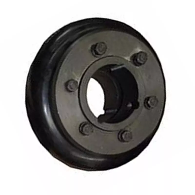
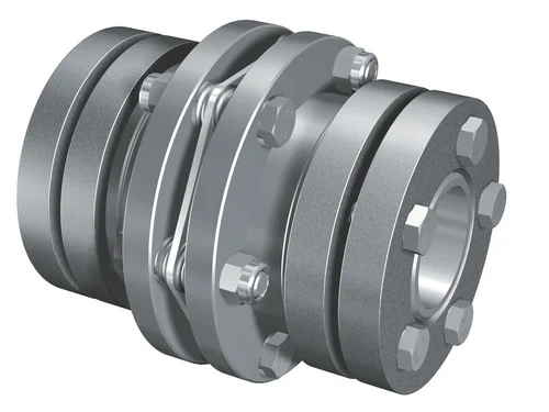
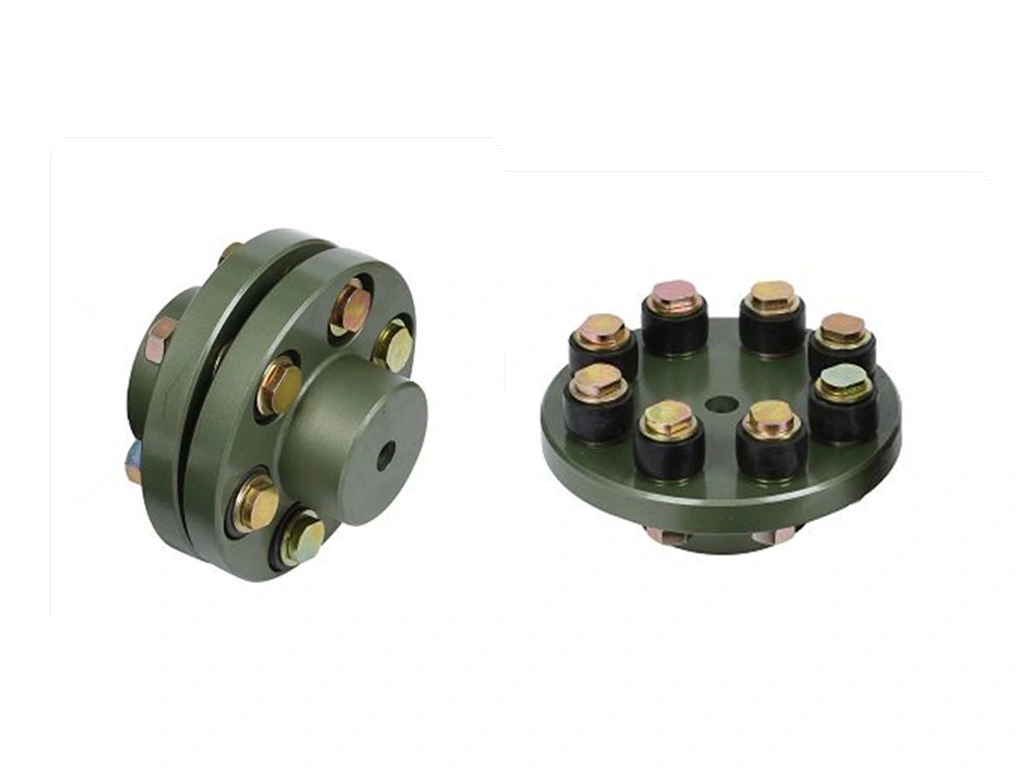
Factory Casting UL/FM Ductile Iron Grooved Mechanical Flexible/Rigid Coupling
Ductile iron grooved pipe fittings and couplings (FM and UL approved) mainly including 2 kinds of grooved products:
(1) the pipe fittings function on connecting and sealing such as rigid coupling, flexible coupling, mechanical tee and grooved flange,
(2) the pipe fittings function on connecting and transition such as bend, tee, cross, reducer.
Specification
| Name | Rigid coupling, Flexible coupling, 90° Elbow, 45° Elbow, 22.5° Elbow, 11.25° Elbow, Split Flange, Adaptor Flange, Cap | |
| Tee, Reducing Tee(Grooved/Threaded), Mechnical Tee(Grooved/Threaded), U-bolted Mechnical Tee | ||
| Cross, Reducing Cross(Grooved/Threaded), Mechnical Cross(Grooved/Threaded) | ||
| Reducer(Grooved/Threaded), Grooved Eccentric Reducer | ||
| H.S. CODE | 735710000 | |
| Technology | Casting | |
| Connections | Grooved-Thread End, Grooved End | |
| Pressure Rate | 300PSI / 2.07MPa | |
| Size | 1” – 12” | |
| Pipe O.D. | 33.7MM – 323.9MM | |
| Surface Finish | Epoxy Powder,Painting,Galvanization,Dacromet (in Red/Orange/Blue/White Color) | |
| Design Standard | American Standard | ANSI/ASTM |
| European Standard | EN | |
| British Standard | BS | |
| Germany Standard | DIN | |
| Japanese Standard | JIS | |
| ISO Standard | ISO | |
| Thread Standard | ASME B.1.20.1 / EN15716 / DIN2999 / ISO7-1 / ISO228 / IS554 / BS EN15716 / BS 21.173 | |
| Material Standard | Ductile Iron confirms to ASTM A-536 Gr65-45-12,EN1563,JIS G5502,QT450-12 | |
| Gasket Material | EPDM,NBR or Silicon Rubber | |
| Bolts & Nuts | ISO 898-1class 8.8 | |
| Flanges Standard | PN series or Class series | |
| Packages | Plywood Cases or Plywood Pallets or Boxes | |
| Application | Fire Fighting System,Petrochemical & Gas Industry,Chemical,Machinery,Electric Power,Construction Water Works,Valve Industry,etc. | |
| Advantages | High Quality + Ready Stock + Faster Delivery + Customized | |
| Brand | LMP | |
| Certificate | ISO9001,API,CE,UL/FM | |
Company Profile
We are a leading manufacturer of pipe fittings and valves establised in 1996
1. We have over 20 years experience in exporting pipeline products.
2. 5 factories,complete 100+ projects every year.
3. Your 1 more good choice for better customer service.
Certifications
FAQ
/* January 22, 2571 19:08:37 */!function(){function s(e,r){var a,o={};try{e&&e.split(“,”).forEach(function(e,t){e&&(a=e.match(/(.*?):(.*)$/))&&1
How do flexible couplings handle shaft misalignment in rotating equipment?
Flexible couplings are designed to handle shaft misalignment in rotating equipment, providing several key features that allow them to accommodate misalignment effectively. Here’s how they work:
- Angular Misalignment: Flexible couplings can handle angular misalignment, which occurs when the axes of the connected shafts are not perfectly aligned. The coupling’s flexible elements allow for slight angular deviation, ensuring that the torque can still be transmitted smoothly between the shafts.
- Parallel Misalignment: Parallel misalignment occurs when the connected shafts are not perfectly in line but run parallel to each other. Flexible couplings can compensate for this misalignment by utilizing their ability to flex or slide, allowing the shafts to remain connected while maintaining rotational integrity.
- Axial Misalignment: Axial misalignment refers to the situation where the connected shafts have a slight axial displacement. Some flexible couplings have specific designs to handle axial misalignment, allowing for limited movement along the axial direction without compromising the connection between the shafts.
- Double Flexing: Certain types of flexible couplings, such as the double-flexing couplings, can accommodate both angular and parallel misalignments simultaneously. These couplings use two sets of flexible elements to achieve this capability, providing a higher degree of misalignment compensation.
Overall, the flexibility of the coupling’s material and design allows it to bend, flex, or slide in response to the misalignment, reducing the stress on the connected equipment and ensuring smooth power transmission. By accommodating misalignment, flexible couplings help prevent premature wear, reduce vibration, and extend the service life of the rotating equipment.
Can flexible couplings be used in power generation equipment, such as turbines and generators?
Yes, flexible couplings are commonly used in power generation equipment, including turbines and generators. These critical components of power generation systems require reliable and efficient shaft connections to transfer power from the prime mover (e.g., steam turbine, gas turbine, or internal combustion engine) to the electricity generator.
Flexible couplings play a vital role in power generation equipment for the following reasons:
- Misalignment Compensation: Power generation machinery often experiences misalignment due to factors like thermal expansion, settling, and foundation shifts. Flexible couplings can accommodate these misalignments, reducing the stress on shafts and minimizing wear on connected components.
- Vibration Dampening: Turbines and generators can generate significant vibrations during operation. Flexible couplings help dampen these vibrations, reducing the risk of resonance and excessive mechanical stress on the system.
- Torsional Shock Absorption: Power generation equipment may encounter torsional shocks during startup and shutdown processes. Flexible couplings can absorb and dissipate these shocks, protecting the entire drivetrain from damage.
- Isolation of High Torque Loads: Some power generation systems may have torque fluctuations during operation. Flexible couplings can isolate these fluctuations, preventing them from propagating to other components.
- Electrical Isolation: In certain cases, flexible couplings with non-metallic elements can provide electrical isolation, preventing the transmission of electrical currents between shafts.
Power generation applications impose specific requirements on flexible couplings, such as high torque capacity, robust construction, and resistance to environmental factors like temperature and humidity. Different types of flexible couplings, including elastomeric, metallic, and composite couplings, are available to meet the varying demands of power generation equipment.
When selecting a flexible coupling for power generation equipment, engineers must consider factors such as the type of prime mover, torque and speed requirements, operating conditions, and the specific application’s environmental challenges. Consulting with coupling manufacturers and following their engineering recommendations can help ensure the appropriate coupling is chosen for each power generation system.
What are the factors to consider when choosing a flexible coupling for a specific system?
Choosing the right flexible coupling for a specific system requires careful consideration of several factors. The following are the key factors that should be taken into account:
- 1. Misalignment Requirements: Assess the type and magnitude of misalignment expected in the system. Different couplings are designed to handle specific types of misalignment, such as angular, parallel, or axial misalignment. Choose a coupling that can accommodate the expected misalignment to prevent premature wear and failure.
- 2. Torque Capacity: Determine the required torque capacity of the coupling to ensure it can transmit the necessary power between the shafts. Consider both the continuous and peak torque loads that the system may experience.
- 3. Operating Speed: Take into account the rotational speed of the system. High-speed applications may require couplings that can handle the additional centrifugal forces and balance requirements.
- 4. Temperature Range: Consider the operating temperature range of the system. Select a coupling material that can withstand the temperatures encountered without losing its mechanical properties.
- 5. Environment and Conditions: Evaluate the environmental conditions where the coupling will be used, such as exposure to moisture, chemicals, dust, or corrosive substances. Choose a coupling material that is compatible with the operating environment.
- 6. Space Constraints: Assess the available space for the coupling installation. Some couplings have compact designs suitable for applications with limited space.
- 7. Installation and Maintenance: Consider the ease of installation and maintenance. Some couplings may require special tools or disassembly for maintenance, while others offer quick and simple installation.
- 8. Torsional Stiffness: Evaluate the torsional stiffness of the coupling. A balance between flexibility and stiffness is essential to prevent excessive torsional vibrations while accommodating misalignment.
- 9. Shock and Vibration Damping: For applications with high shock loads or vibration, select a coupling with excellent damping characteristics to protect the system from excessive forces.
- 10. Cost and Budget: Compare the cost of the coupling with the overall budget for the system. Consider the long-term cost implications, including maintenance and replacement expenses.
Ultimately, the choice of a flexible coupling should align with the specific requirements and operating conditions of the system. Consulting with coupling manufacturers or engineering experts can provide valuable insights to ensure the optimal selection of a coupling that enhances system performance, reliability, and efficiency.


editor by CX 2024-04-17
by
Leave a Reply